multiwire probing setup
Aug 31, 2024 Andreas Fell
This example simulates the FF artifact when using alternating current / voltage wires to measure a solar cell
3D view of bifacial busbarless cell with alternating current / voltage wires
The "Probe" functionality is used to define a voltage for the JV calculations which is different from the default applied voltage, thereby representing a 4-wire measurement.
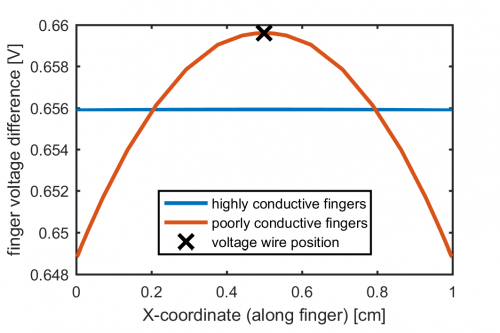
Alternating current / voltage wires with an equal spacing of 5mm are assumed, which means the voltage is sensed between the current wires. Due to current flow along the fingers towards the current wires, the voltage has a maximum precisely at the voltage sense wire. This maximum exceeds the mean voltage for the case of very highly conductive fingers, which explains the overestimation of FF and efficiency in such a contacting setup. It therefore becomes beneficial to use more poorly conductive fingers (i.e. higher Rsheet in the figure below) to increase measured efficiency.
